The Engineering of Quasi-Continuous-Wave Tesla Coils
Why QCW Dual Resonant Solid State Tesla Coils are considered the pinnacle of amateur resonant power electronics, and how a simple change in operating philosophy transforms the engineering challenge into a tightly coupled nonlinear control problem.
26
minutes
5,166
words approx.
7
indexed topics
03 JUL
2026
Quasi-Continuous-Wave Dual Resonant Solid State Tesla Coils: The Pinnacle of Resonant High-Voltage Engineering
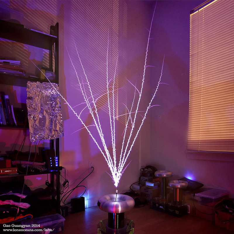
Quasi-Continuous-Wave Dual Resonant Solid State Tesla Coils (QCW DRSSTCs) are widely regarded as the holy grail of modern Tesla coil design. Capable of producing metre-scale electrical discharges with exceptional electrical efficiency while simultaneously reproducing remarkably faithful audio through nothing more than ionised air, they represent a convergence of resonant power electronics, embedded control systems, electromagnetics, and plasma physics unlike almost any other engineering project.
At first glance, the leap from a conventional Dual Resonant Solid State Tesla Coil (DRSSTC) to its QCW counterpart appears surprisingly modest. The resonant bridge remains fundamentally unchanged, the primary and secondary resonators continue to operate on the same physical principles, and the feedback architecture is largely familiar to experienced DRSSTC designers. The most obvious addition is a programmable high-voltage DC bus supply capable of smoothly ramping the bridge voltage rather than applying it instantaneously.
Yet this seemingly modest change transforms the machine entirely.
QCW DRSSTCs have earned a reputation for being among the most demanding Tesla coil topologies to design successfully — not because they contain dramatically more hardware, but because every subsystem must now operate within a continuously evolving electrical system. Rather than designing around a single operating point, engineers must instead consider the dynamic interaction between resonant energy transfer, semiconductor switching, magnetic coupling, thermal behaviour, and the changing electrical characteristics of an actively growing plasma discharge.
While I haven't yet built a system of this complexity, I find QCW DRSSTCs to be one of the most fascinating case studies in coupled-system engineering. This article breaks down the underlying physics and control theory to explore what distinguishes QCW DRSSTCs from other architectures, why they are considered the "holy grail" of resonant high-voltage engineering, and why such a seemingly incremental evolution introduces a disproportionately large engineering challenge.
The Evolution of the Tesla Coil
The history of Tesla coil development can be viewed as a gradual progression towards greater efficiency, controllability, and energy utilisation. Each successive topology builds upon the strengths of its predecessor while introducing increasingly sophisticated methods of controlling resonant energy transfer.
Spark Gap Tesla Coils (SGTC)
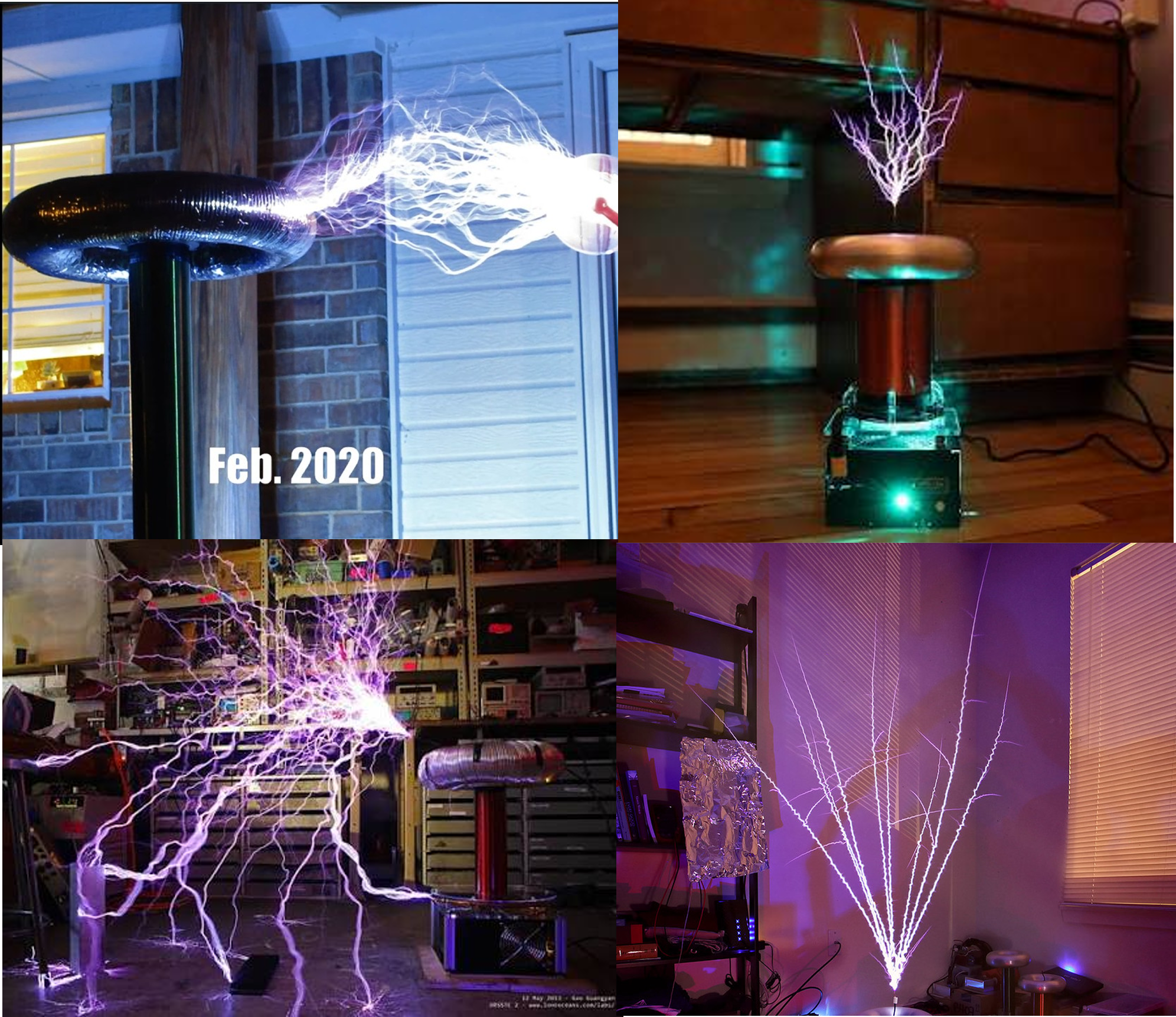
The original spark-gap Tesla coil remains the most recognisable implementation of Nikola Tesla's resonant transformer concept. Energy is stored within a high-voltage capacitor before being released through a spark gap into the primary resonant circuit, producing oscillating currents that magnetically couple energy into the secondary resonator.
Despite their relative simplicity and ability to generate spectacular electrical discharges, SGTCs suffer from several inherent limitations. The spark gap dissipates a significant proportion of the stored energy as heat, switching occurs with little control or repeatability, and the system provides virtually no opportunity for active feedback or protection. The result is a machine capable of producing impressive arcs, but with comparatively poor efficiency and limited operational flexibility.
Solid State Tesla Coils (SSTCs)
Replacing the spark gap with semiconductor switches represented a significant advance in Tesla coil technology. By actively driving the primary resonator using MOSFETs or IGBTs, SSTCs achieve substantially greater efficiency while introducing precise electronic control over frequency, burst duration, and protection mechanisms.
This transition also enables one of the most recognisable features of modern Tesla coils: musical playback. By modulating the interrupter frequency, the plasma itself becomes an acoustic transducer, producing sound through the rapid heating and expansion of the surrounding air.
However, because the primary circuit lacks the large-tank energy storage characteristic of a DRSSTC, achievable primary currents—and therefore spark lengths—remain comparatively limited.
Dual Resonant Solid State Tesla Coils (DRSSTCs)
The defining innovation of the DRSSTC is the introduction of resonance on both the primary and secondary circuits. Unlike an SSTC, where the primary is directly driven, a DRSSTC incorporates a primary resonant capacitor () together with the primary inductance () to form a resonant tank circuit:
When the inverter drives this resonant system near its operating frequency, energy oscillates between the magnetic field of the inductor and the electric field of the capacitor. Crucially, the bridge does not directly create the output voltage. Instead, it compensates for system losses and replenishes the energy dissipated through winding resistance, semiconductor conduction, switching losses, and plasma loading.
This allows the circulating current within the primary tank to become significantly larger than the current drawn from the DC supply. Peak primary currents exceeding several hundred amperes are common, while larger systems can reach into the kiloampere range.
This dramatic improvement in resonant energy utilisation made DRSSTCs the preferred architecture for builders seeking maximum performance while retaining electronic control.
The QCW Philosophy
QCW DRSSTCs challenge one of the fundamental assumptions underlying conventional DRSSTC operation. A traditional DRSSTC typically applies a fixed DC bus voltage for a short burst lasting only a few hundred microseconds. The inverter delivers energy into the resonant system, the primary current rises rapidly, and the burst terminates before the overall electrical characteristics of the system change significantly.
A QCW system deliberately operates differently. Instead of applying a constant voltage, the DC bus is gradually increased over a much longer period, typically between 10ms and 50ms. This controlled energy delivery allows the electrical discharge to develop progressively rather than appearing as a rapidly expanding burst of streamers.
| Conventional DRSSTC Operation | QCW DRSSTC Operation |
|---|---|
| Fixed DC bus excitation | Time-varying DC bus trajectory |
| Rapid primary current rise | Controlled current evolution |
| Discrete energy transfer into secondary | Continuous energy transfer throughout burst |
| Streamer formation | Streamer-to-leader transition |
Initially, the secondary produces small streamer discharges similar to those observed in conventional Tesla coils. As energy continues to be supplied, these streamers heat the surrounding air, increase in conductivity, and transition into stable leader channels capable of extending significantly further through the atmosphere. Top-tier QCW systems have achieved leader lengths exceeding 2 to 3 metres from power supplies drawing only a few kilowatts.
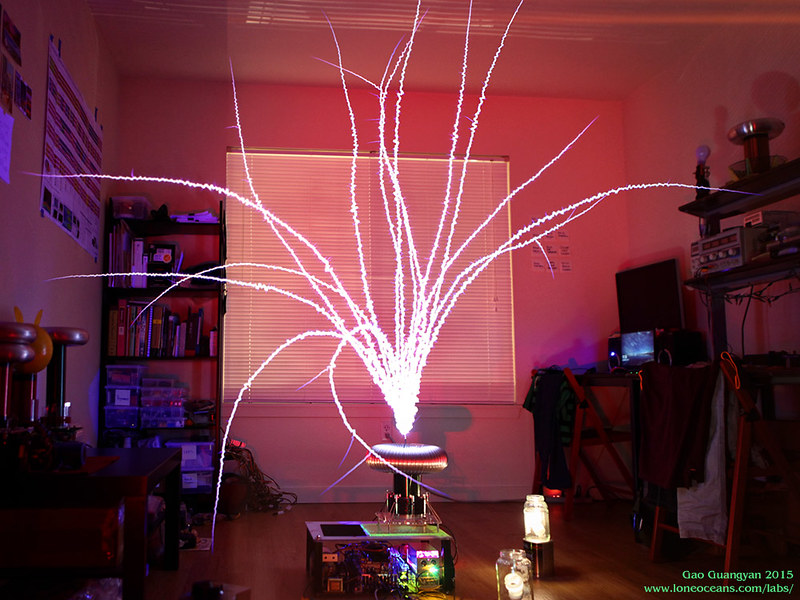
The resulting discharge differs substantially from the branching arcs produced by conventional Tesla coils. Rather than producing numerous short-lived streamers, QCW systems create long, smooth, intensely luminous plasma channels that more closely resemble the leader structures observed during natural lightning formation. The visual result is spectacular. The engineering required to produce it is considerably more complex.
A Moving Operating Point
The principal challenge associated with QCW operation is that the machine no longer operates around a single, approximately constant operating condition.
In a conventional DRSSTC, the bridge applies a fixed bus voltage, current rises predictably within the primary tank, energy transfers to the secondary, and the burst terminates before the overall system changes appreciably.
A QCW DRSSTC deliberately abandons this behaviour.
Throughout a single burst:
- the DC bus voltage continuously increases,
- primary current evolves continuously,
- semiconductor heating accumulates,
- magnetic coupling changes,
- plasma conductivity changes,
- streamer loading evolves into leader loading,
- and the effective electrical characteristics of the secondary system change alongside the growing discharge.
The key difference is that these effects do not occur independently. A QCW burst represents a continuously evolving interaction between electrical, thermal, electromagnetic, and plasma domains:
The consequence is that previously separable subsystems become strongly coupled through this shifting operating point. The bridge is no longer driving a relatively fixed resonant converter. Instead, it is controlling a nonlinear, time-varying system whose parameters mutate continuously throughout the duration of the burst.
System Architecture
Although QCW DRSSTCs are often discussed primarily in terms of their spectacular electrical discharges, the visible arc represents only the final stage of a much larger energy conversion system.
At their core, these machines are highly specialised resonant power converters. They combine controlled energy delivery, high-frequency switching, magnetic coupling, and real-time feedback control to manipulate the evolution of a plasma discharge.
A simplified QCW DRSSTC architecture can be understood through three primary power-conversion stages, unified by a continuous digital control layer
Each stage performs a distinct function, but the behaviour of the complete system emerges from the interaction between them.
Power Conversion and Achieving the QCW Effect
The defining operational difference between a conventional DRSSTC and a QCW DRSSTC is the temporal profile of the energy delivery. A conventional DRSSTC operates from a fixed bus voltage (), whereas a QCW system treats the DC bus as an active control variable ().
The voltage profile is deliberately shaped over time—typically as a linear or exponential ramp—to control the rate at which energy enters the resonant system. While this ramped voltage is the fundamental requirement, there are three distinct hardware topologies used to achieve it, each with significant engineering trade-offs:
| Topology | Energy Modulation Method | Advantages | Disadvantages |
|---|---|---|---|
| Buck Converter | Ramps the DC bus voltage before the H-bridge. | Preserves ZCS, highest efficiency, excellent scalability. | Large inductors and capacitors, increased cost and size. |
| Phase-Shifted Bridge | Varies the effective voltage applied by changing the phase relationship between bridge legs. | Eliminates the buck converter, compact implementation. | Partial hard-switching, significant thermal stress, limited scalability. |
| Delta-Sigma Modulation | Modulates primary current by varying the controller's current reference. | Minimal additional hardware, simple implementation. | Experimental approach with few documented high-power systems; regulates current rather than voltage. |
1. Bus Modulator (Buck Converter) Method
The most straightforward approach is to place a high-power buck converter between the mains rectification stage and the H-bridge. By modulating the duty cycle of the buck converter, the bus voltage smoothly ramps up over the 10–50 ms burst duration.
The primary advantage of this method is that the resonant inverter continues to operate with zero-current switching (ZCS), minimising switching losses. At larger power levels, interleaved buck topologies are used to distribute current and reduce output ripple.
The challenge is physical size and power handling. The buck converter must be capable of supplying the massive currents required by the bridge (often 100–200 A) while relying on physically large filter inductors and capacitors. However, because it preserves soft-switching, this method is generally considered the most scalable and produces the highest efficiency.
2. Phase-Shifted Bridge Method
To eliminate the large, heavy buck converter entirely, some builders use a phase-shifted bridge topology. In this configuration, the H-bridge driving the primary coil is not switched in perfect opposition. Instead, the phase relationship between the two bridge legs is progressively modulated over time. This effectively varies the voltage applied across the primary resonant tank, achieving the same gradual energy ramp without a dedicated bus modulator.
The significant drawback is that half of the transistors in the bridge are subjected to hard-switching under high current. This generates substantial thermal stress, pushing the semiconductors to their operational limits. To manage this, builders such as Steve Ward and Phillip Slawinski have connected multiple bridges and primaries in parallel—sometimes using 16 or more transistors—to share the hard-switched current burden. While this yields a highly compact system with excellent performance, the cost, complexity, and thermal management requirements make scaling to higher power levels increasingly difficult.
3. Delta-Sigma Modulation Method
A third, more experimental approach proposed by Steve Conner involves modifying the feedback controller itself. Instead of ramping the hardware bus voltage, a conventional DRSSTC controller's over-current detector is supplied with a ramping reference voltage. The result is a delta-sigma modulation scheme in which the interrupter allows burst pulses through with a varying duty cycle, causing the primary current to ramp approximately linearly in response to the changing current setpoint.
While this method requires very little additional hardware, it regulates current directly rather than voltage, and there are relatively few documented working systems using this topology at the time of writing.
The Impact on System Architecture
Regardless of which of the three topologies is employed, the consequence for the rest of the system is essentially identical. The buck converter (or alternatively the phase-shifted bridge or delta-sigma controller) is not simply a power supply; it functions as an energy modulation stage. Its output waveform directly determines how quickly primary current develops and, consequently, how aggressively the plasma discharge evolves.
A simplified relationship between the available input power and the bus conditions is
Increasing the effective bus voltage increases the energy available to the inverter. However, the relationship between bus voltage, primary current, and spark development is highly nonlinear because the electrical properties of the plasma continuously evolve as the discharge grows.
The Resonant Inverter
Following the programmable DC bus is the high-current switching bridge, typically implemented using high-power IGBTs or silicon carbide (SiC) MOSFETs.
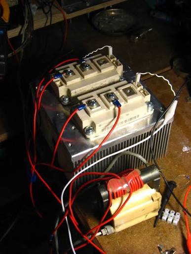
Unlike a conventional switching converter designed to directly generate a specific output voltage, this inverter acts purely as an AC excitation source for the primary tank. As established in the DRSSTC architecture, its primary role is loss compensation. By injecting energy precisely in phase with the tank's natural oscillation, the inverter allows circulating currents to build to extremes—often exceeding a thousand amperes in larger systems—despite drawing comparatively moderate power from the DC bus.
Resonant Energy Transfer
When the two resonant systems are correctly tuned, energy transfers efficiently between them, causing the voltage at the secondary terminal to increase until the electric field exceeds the breakdown strength of air. At this point, the Tesla coil transitions from a purely electromagnetic system into a coupled electromagnetic-plasma system. The discharge is no longer merely a result of the resonator; it becomes part of the resonator itself, actively shifting the system's operating parameters as it grows.
Feedback and Control
Maintaining stable operation requires continuous feedback. The inverter must remain synchronised with the resonant system while compensating for nanosecond-scale delays introduced by switching devices, gate drivers, current sensors, and logic propagation.
In practice, this is typically achieved using a Phase-Locked Loop (PLL) implemented on a fast microcontroller or FPGA. The PLL continuously tracks the zero-crossings of the primary tank current, dynamically adjusting the inverter's switching frequency to maintain Zero-Current Switching (ZCS). By switching exactly when current crosses zero, semiconductor turn-off losses are reduced and electrical stress is minimised.
A typical QCW DRSSTC control architecture must simultaneously manage:
- Primary current feedback and over-current protection
- PLL-based phase tracking and compensation
- Interrupter timing and burst duration
- Closed-loop buck converter modulation for the DC bus ramp
However, QCW operation introduces an additional difficulty: the resonant system itself changes throughout the burst. The controller cannot simply lock onto a fixed frequency; it must track a moving target as the plasma load alters the secondary characteristics:
Because the controller is required to maintain correct ZCS behaviour while the electrical system it is actively tracking continuously mutates, QCW DRSSTCs cannot be treated as open-loop high-voltage generators. They are dynamic resonant control systems.
Why QCW Systems Are So Difficult
One of the most common misconceptions surrounding QCW Tesla coils is that they differ from conventional DRSSTCs only through the addition of a programmable high-voltage power supply. While this is technically true from a hardware perspective, it significantly understates the engineering challenge.
The difficulty does not come from the presence of any individual difficult component. High-power switching devices, resonant tanks, and feedback controllers are all mature, well-understood technologies.
The difficulty comes from their interaction during a continuously changing operating point. Because the electrical environment shifts from millisecond to millisecond, the stress placed on the control architecture is relentless.
For example:
- Feedback systems must maintain accurate phase information while the resonant behaviour mutates.
- Inverter timing must remain close to zero-current switching (ZCS) conditions to minimise losses, even as the target frequency drifts.
- Over-current protection must be intelligent enough to distinguish between an intentional, expected current ramp and a genuine fault condition.
- Thermal design must account for semiconductor losses that accumulate far longer than in a conventional DRSSTC, as both current amplitude and conduction time increase simultaneously.
A QCW DRSSTC is a nonlinear, time-varying resonant system. Designing such a machine requires understanding not only how each subsystem functions independently, but how changes within one domain propagate through the entire system. To understand the root cause of these shifting parameters, we have to look at what the coil is actually creating.
Engineering the Plasma
The most visually striking feature of a QCW DRSSTC is the exceptionally long, stable electrical discharge it produces. However, the length of the spark is not simply a consequence of increased voltage or higher peak current.
The defining advantage of QCW operation is the ability to control the physical evolution of the plasma channel itself.
A conventional Tesla coil primarily creates streamer discharges. These are short-lived ionisation paths formed when the electric field at the terminal exceeds the breakdown strength of the surrounding air. Because the discharge exists only briefly, energy is continuously spent creating new ionised paths rather than extending existing ones.
QCW operation changes this behaviour by controlling the rate at which energy is deposited into the discharge. The objective is not to maximise instantaneous power, but to deliver energy at a rate that allows a stable plasma channel to develop.
Streamer Formation and Leader Development
The initial discharge from a Tesla coil begins as a collection of streamer channels extending from the high-voltage terminal.
At this stage, the plasma is relatively cold and weakly conductive. Energy is required primarily to accelerate free electrons, ionise additional air molecules, and extend the ionisation path. Furthermore, the accumulation of space charge from this initial corona and streamer activity significantly distorts the local electric field surrounding the terminal. This distortion creates an unpredictable, highly non-uniform environment that can either facilitate or hinder the transition to a leader, adding another layer of complexity to the initial conditions the QCW controller must navigate.
As energy continues to be deposited, one or more streamer paths may begin to dominate. The temperature within these channels increases as electrical current flows through the partially ionised gas.
If the energy input exceeds the rate at which heat can be removed through conduction, convection, and radiation, the channel undergoes thermal runaway. The gas temperature rises rapidly, increasing the degree of ionisation and therefore reducing electrical resistance.
This creates a positive feedback process:
The result is the formation of a thermalised leader channel—a highly conductive, intensely luminous plasma structure that behaves very differently from the initial cold streamer.
Thermal Ionisation and Conductivity
A mature leader channel differs fundamentally from a cold streamer.
The gas inside the channel is heated progressively. The transition to a stable leader in atmospheric air does not wait for full thermal equilibrium; it actually begins at lower temperatures—typically between and depending on current density and pressure—driven by non-equilibrium processes. However, once the channel temperature exceeds approximately , full thermalisation occurs. At this point, governed by the Saha equation, the concentration of charged particles increases by orders of magnitude, transforming the channel from a weakly conducting ionisation path into a highly conductive plasma structure.
The electrical resistance of this channel can decrease by several orders of magnitude compared with the initial streamer. This transition is critical because it changes how energy is used.
After leader formation:
The system no longer needs to repeatedly break down fresh air. Instead, energy is concentrated into maintaining and extending an existing conductive path. This is the physical reason QCW systems can produce metre-scale discharges without requiring the extreme peak currents that would otherwise be expected. The coil is not forcing electricity through cold air. It is extending an already established plasma pathway.
Plasma as a Dynamic Electrical Component
From an engineering perspective, the most interesting aspect of leader formation is that the plasma cannot be treated as a passive load. Its electrical properties evolve throughout the discharge, fundamentally altering the behavior of the resonant circuit.
The growing leader modifies the effective secondary capacitance, the secondary quality factor, the resonant frequency, the energy transfer efficiency, and the phase relationship between the primary and secondary systems.
As the leader extends, the capacitance contribution from the discharge increases. The effective secondary capacitance becomes:
This additional capacitance causes the secondary resonant frequency to decrease proportionally as the discharge grows:
This frequency shift explains why maintaining optimal operation throughout a QCW burst is significantly more challenging than in a conventional DRSSTC. The controller is not only regulating a power converter; it is actively compensating for the changing electrical properties of a growing plasma structure.
Controlled Energy Delivery
The success of a QCW DRSSTC therefore depends on carefully balancing energy input and plasma development.
If energy is introduced too rapidly, the discharge may become unstable, producing excessive current, premature breakdown, or destructive loading on the inverter.
If energy is introduced too slowly, the discharge may fail to transition from streamer formation into a stable leader, limiting achievable length.
The voltage ramp generated by the buck converter is therefore a critical design parameter. It determines the rate at which energy becomes available and influences the entire evolution of the discharge.
The optimal ramp is not necessarily the one that produces the highest peak current.
It is the one that maintains the correct relationship between:
- energy supplied,
- plasma growth,
- resonant operation,
- and semiconductor limitations.

This represents a fundamental shift in Tesla coil design philosophy.
Rather than simply generating the highest possible electric field, QCW systems attempt to actively control the development of the discharge itself.
Artificial Lightning Through Control Theory
Natural lightning follows a similar physical principle.
A lightning leader does not instantaneously create a conductive path between cloud and ground. Instead, it develops through a sequence of ionisation events, thermal processes, and conductive channel growth.
A QCW DRSSTC recreates a simplified version of this process under controlled laboratory conditions.
The difference is that instead of relying on atmospheric electric fields and natural charge separation, the engineer controls the process through:
- semiconductor switching,
- resonant energy transfer,
- feedback control,
- and precisely shaped power delivery.
This is what makes QCW systems particularly fascinating. Because they are not simply machines that generate high voltage. But systems designed to control the formation and evolution of artificial plasma structures.
Comparing Tesla Coil Architectures
This control-focused perspective provides the clearest lens through which to view the historical progression of Tesla coil topologies. The progression from SGTC to QCW DRSSTC is ultimately a progression from passive energy transfer toward active control.
Each topology solves a different engineering problem. Spark-gap systems prioritise simplicity and robustness, solid-state systems introduce precise electronic control, DRSSTCs maximise resonant energy utilisation, and QCW systems extend this control into the temporal evolution of the plasma discharge itself.
The primary differences are not simply in output power, but in how much of the system behaviour is actively controlled.
| Feature | SGTC | SSTC | DRSSTC | QCW DRSSTC |
|---|---|---|---|---|
| Switching mechanism | Gas discharge spark gap | MOSFET / IGBT bridge | High-current IGBT / SiC bridge | High-current bridge with programmable DC bus modulation |
| Primary excitation | Resonant capacitor discharge | Directly driven primary | Dual resonant primary tank | Dual resonant primary tank with controlled energy ramp |
| Bus profile | Capacitor discharge waveform | Fixed DC bus | Fixed DC bus | Time-varying controlled voltage ramp |
| Energy control | Passive | Frequency and interruption control | Current-limited resonant energy transfer | Closed-loop energy trajectory control |
| Typical burst duration | Microseconds | Microseconds to milliseconds | Tens to hundreds of microseconds | Tens to hundreds of milliseconds |
| Resonant control complexity | Low | Moderate | High | Very high |
| Primary current | Tens to hundreds of amperes | Tens to hundreds of amperes | Hundreds to thousands of amperes | Hundreds to thousands of amperes with controlled growth |
| Plasma behaviour | Short branching streamers | Smaller controlled discharges | High-energy streamer arcs | Thermally developed leader channels |
| Audio capability | Limited | Good | Excellent | Excellent |
| Engineering challenge | Low | Moderate | High | Extremely high |
The most important distinction between these architectures is not the magnitude of the electrical output, but the level of control exercised over the energy transfer process.
- A spark-gap Tesla coil allows the physics of the resonant circuit to determine the behaviour of the discharge.
- An SSTC introduces control over excitation.
- A DRSSTC introduces control over resonant energy storage.
- A QCW DRSSTC introduces control over the evolution of the discharge itself.
This represents the fundamental engineering progression: moving from generating electrical energy, to controlling electrical energy, to actively shaping the behaviour of a nonlinear physical system.
Beyond High Voltage Engineering
Although QCW DRSSTCs have limited practical applications outside research, education, and technical demonstration, they represent an unusually rich engineering case study.
The significance of these systems is not found solely in their ability to produce extreme voltages or metre-scale electrical discharges. Their real value lies in the way they combine several areas of engineering that are normally studied independently.
A QCW DRSSTC requires the designer to consider:
- high-frequency power conversion,
- resonant circuit analysis,
- semiconductor switching behaviour,
- magnetic coupling,
- real-time feedback control,
- thermal management,
- electromagnetic compatibility,
- and plasma physics.
However, the most interesting aspect is not the presence of these individual disciplines. Each field contains mature technologies and well-established design methods.
The challenge is the interaction between them.
A conventional engineering approach often divides complex systems into separate subsystems: a power stage, a controller, a mechanical structure, or a sensor network. Each component can be designed, tested, and optimised independently before integration.
QCW DRSSTCs challenge this approach:
- The electrical behaviour of the plasma affects the resonant system.
- The resonant system affects the inverter operating point.
- The inverter operating point affects semiconductor losses and thermal behaviour.
- The thermal behaviour influences reliability and allowable operating limits.
- The controller must then account for all of these interactions simultaneously.
The result is a system where the boundary between "plant" and "controller" becomes less clearly defined. The object being controlled is not a fixed machine with predictable parameters, but a continuously evolving physical process.
And ultimately this is what makes QCW DRSSTCs an excellent example of modern engineering system design.
Many advanced engineering problems share the same characteristic: the difficulty does not come from a lack of individual technologies, but from integrating many individually understood technologies into a system that behaves correctly as a whole.
This is seen in fields such as:
- aerospace systems,
- autonomous robotics,
- high-performance electric machines,
- semiconductor manufacturing,
- and advanced energy conversion.
In each case, success depends not only on understanding individual components, but on understanding the relationships between them.
A QCW Tesla coil therefore represents something more interesting than a high-voltage demonstration device.
It is a compact example of a larger engineering principle:
Advanced systems rarely fail because of a single impossible component. They are difficult because many manageable components must operate together under tightly coupled constraints.
The QCW DRSSTC is a particularly visible demonstration of this idea. A machine that appears externally to be little more than a coil producing lightning is, internally, a carefully coordinated interaction between power electronics, control algorithms, electromagnetic fields, and plasma dynamics.
That combination is what makes the technology so fascinating—not simply the ability to create artificial lightning, but the engineering required to control it.
Final Thoughts
Quasi-Continuous-Wave Dual Resonant Solid State Tesla Coils represent one of the most fascinating examples of modern resonant power engineering. At first glance, they appear to be a natural evolution of the Tesla coil: a more powerful version of an already impressive high-voltage device. However, the deeper engineering reveals something considerably more interesting.
The defining achievement of a QCW DRSSTC is not simply the generation of larger electrical discharges. It is the ability to actively influence the behaviour of a complex physical system by controlling the flow of energy into it. Through the combination of programmable power conversion, resonant energy transfer, real-time feedback, and careful control of plasma development, the system transforms a chaotic electrical phenomenon into a predictable and repeatable engineering process.
This transition—from producing high voltage to controlling the evolution of a plasma discharge—is what separates QCW DRSSTCs from earlier Tesla coil designs. They demonstrate a broader principle found throughout advanced engineering: performance rarely comes from a single breakthrough component. Instead, it emerges from the careful integration of many systems that must operate together under demanding conditions.
Analyzing systems like this—even purely from a theoretical and research standpoint—is an invaluable exercise for any engineer. It sharpens the ability to recognize coupled constraints, a skill that translates directly into aerospace, robotics, advanced energy conversion, and beyond. The visible result is a lightning-like electrical discharge, but the true engineering achievement is the invisible system behind it.
References & Further Reading
For those interested in diving deeper into the control theory and physics discussed in this article, the following resources were instrumental in this analysis:
Primary Builder Resources:
- Loneoceans Laboratories (Gao Guangyan) - QCW Theory: Detailed experimental data on the buck converter method, streamer-to-leader transition, and primary current management. https://www.loneoceans.com/labs/qcw/
- Loneoceans Laboratories (Gao Guangyan) - UD2.7 Universal Driver: A modern, open-source implementation of the DRSSTC feedback controller. This page details the hardware architecture behind the phase-locked loop (PLL) tracking and intelligent over-current protection (OCD) systems required for complex QCW operation. https://www.loneoceans.com/labs/ud27/
- Loneoceans Laboratories - Phase Shift QCW: Comprehensive documentation of the alternative phase-shifted bridge method. http://www.loneoceans.com/labs/qcw2/
- Steve Ward's Phase-Shift QCW (Forum Archive): Primary documentation of Steve Ward and Phillip Slawinski's multi-bridge, hard-switched QCW architectures. https://highvoltageforum.net/index.php?topic=1672.0
- Steve Conner's Delta-Sigma QCW (Forum Archive): The original discussion thread proposing the delta-sigma ramping method.
- The High Voltage Forum - General DRSSTC Discussion: The modern hub for top builders there are some threads discussing QCW PLL tracking, ramp generation, and control theory. https://highvoltageforum.net/index.php?board=11.0
Academic Literature on Leader Propagation & Plasma Physics:
- Raizer, Y. P. "Gas Discharge Physics". The definitive textbook on the transition from streamer to leader, non-equilibrium ionisation, and plasma conductivity. (Springer).
- Les Renardières Group, "Long Air Gap Discharges at Les Renardières" (Electra, 1972-1977). A classic, multi-part series of papers documenting how laboratory-generated long sparks develop via leader propagation and space charge distortion. (IEEE Xplore/CIGRE).
- Cooray, V. "The Lightning Flash". While focused on natural lightning, the chapters on leader initiation and the Saha equation perfectly mirror the physics occurring at the top load of a QCW DRSSTC. (IET).