THEORETICAL DESIGN · VALIDATED SIMULATION
Hydraulic Radial Piston Motor Design and Optimization
Theoretical multi-physics design of a radial piston motor — full parametric CAD, FEA structural analysis, and a medium fidelity simulation and optimisation engine validated against 450 bar transient fluid campaigns.
Non-linear multi-physics design and optimization of a hydraulic radial piston motor for mining applications, integrating fluid dynamics, structural analysis, and thermal management to achieve optimal efficiency and reliability under extreme operating conditions.
Contribution Matrix
Breakdown of individual contributions and responsibilities for this collaborative project.
Lead Systems Engineer
2 Students
12 weeks
This project was completed collaboratively with one other team member. The engineering work presented below clearly distinguishes between my individual contributions and those completed by my teammate.
Technical Writing
Detailed sections of my work outlining the engineering process, analysis, and outcomes.
01Project Overview
Project Overview
This project details the end-to-end design, physics-based modeling, and optimization of a high-torque radial piston hydraulic motor. The objective was to minimize output torque ripple and pressure pulsation while maintaining structural integrity and volumetric efficiency under high-pressure cyclic loading (~450 bar).
The scope encompasses the comparative architectural selection of motor configurations, the derivation of a reduced-order coupled hydraulic-mechanical mathematical model, and the development of a hybrid Bayesian optimization framework to synthesize the cam profile geometry. The final output is a validated seven-piston, six-lobe cam-ring motor architecture, supported by transient hydraulic simulations, nonlinear finite element analysis (FEA), and full system-level integration testing.
03Problem Definition
Problem Definition
The fundamental engineering challenge in radial piston motor design is the mitigation of torque ripple and pressure pulsation within a tightly coupled, nonlinear multiphysics system. Unlike continuously distributed torque systems, radial piston motors generate mechanical rotation through a finite number of discrete hydraulic chambers. Each piston produces a local force contribution whose magnitude varies continuously with piston displacement, chamber pressure, contact angle, local cam curvature, and hydraulic commutation behaviour.
The performance of these systems is governed by the sequential nonlinear mapping of design parameters to dynamic output:
where is the design vector, is the cam profile, is the piston displacement, is the chamber pressure, and is the output torque. This mapping introduces inherent dynamic complexity through three primary physical mechanisms.
Compressibility-Induced Oscillations. The hydraulic fluid behaves as a stiff spring within each chamber. Chamber pressure evolution is governed by the balance between piston-induced volume change, valve flow, and fluid compressibility (bulk modulus, ). Because the pistons are driven by a discrete cam profile, the rate of volume change, , is inherently non-uniform.
When the piston expands the chamber faster than fluid can enter, the chamber pressure decreases. Conversely, when piston motion slows or reverses, pressure rises rapidly. The chamber therefore behaves as a coupled mass-spring-damper system, where the effective hydraulic stiffness is:
with denoting fluid bulk modulus, representing piston area, and indicating equivalent chamber volume. The interaction between this hydraulic stiffness and piston inertia produces oscillatory pressure dynamics that directly manifest as pressure ripple.
Discrete Firing Harmonic Reinforcement. The total output torque is the superposition of multiple phase-shifted piston force contributions. Since these excitation events are periodic, the harmonic structure of the torque waveform is governed primarily by the relationship between the piston count, , and the cam lobe count, .
If these quantities share a common divisor, repeated phase alignment occurs over successive revolutions. This synchronous reinforcement produces coherent low-order harmonic peaks. These low-frequency oscillations are particularly undesirable because they:
- Drivetrain Coupling: Couple strongly into the drivetrain inertia.
- Torque Ripple: Produce noticeable torque ripple.
- Weak Attenuation: Are only weakly attenuated by hydraulic damping.
Selecting coprime piston and lobe counts therefore provides an effective mechanism for distributing excitation energy across higher harmonic orders, reducing coherent reinforcement.
Geometric-Hydraulic Coupling. The cam profile simultaneously governs both the mechanical and hydraulic behaviour of the motor. Mechanically, it determines contact pressure, pressure angle, piston velocity, piston acceleration, jerk, and local curvature. Hydraulically, it defines chamber volume evolution and therefore controls pressure generation as mapped below:
These objectives are inherently coupled. A cam profile that minimises hydraulic pressure ripple may introduce excessive curvature gradients that increase contact stress, violate fatigue limits, or cause boundary lubrication breakdown. Conversely, a mechanically conservative profile generally exhibits poorer harmonic dispersion and increased pressure pulsation.
Design Reality: Radial piston motor design cannot be approached as the independent optimisation of isolated parameters. Instead, it requires the coordinated balancing of competing physical constraints across multiple engineering domains simultaneously.
Tightly Coupled Multiphysics Landscape. The resulting design landscape is highly nonlinear and strongly non-convex, meaning improvements in one performance metric frequently degrade another. Key cross-domain areas requiring simultaneous balance include:
- Harmonic & Hydraulic Balance: Harmonising harmonic behaviour alongside dynamic hydraulic stability.
- Structural Integrity: Verifying structural durability against local contact mechanics.
- Production Viability: Ensuring manufacturability while maximizing overall volumetric efficiency.
For example, reducing internal leakage increases volumetric efficiency but simultaneously decreases hydraulic damping. This unintended loss of damping potentially amplifies pressure oscillations and torque ripple. This complex interplay motivates the development of holistic optimisation frameworks capable of evaluating the complete interaction between geometry, hydraulics, and structural dynamics rather than treating each subsystem independently.
04Requirements
Requirements
The motor was designed against a set of competing criteria prioritised for high-torque, low-speed industrial applications. The selected architecture needed to support detailed multiphysics modelling while providing clear relationships between geometric design parameters and dynamic performance metrics. In particular, the design was expected to facilitate optimisation across hydraulic, mechanical, and structural domains without introducing unnecessary modelling complexity.
Unweighted Design Criteria Assessment. The candidate architectures were first evaluated qualitatively against the key design objectives.
| Criteria | Eccentric | Cam Ring | Crankshaft | Phased Rotor |
|---|---|---|---|---|
| Torque Smoothness | Very Low | Moderate | Moderate–High | Very High |
| Pressure Stability | Moderate | Moderate–High | High | Moderate–High |
| Structural Simplicity | High | Moderate–High | Moderate | Low |
| Durability | Moderate | High | Moderate–High | High |
| Efficiency | Low | Moderate–High | Moderate–High | High |
| Packaging Efficiency | High | Moderate–High | Moderate | Moderate |
| Manufacturing Ease | High | Moderate–High | Moderate | Low |
| Control Simplicity | High | Moderate | Moderate | Low |
| Thermal Performance | Low | Moderate–High | Moderate–High | High |
| Tolerance Robustness | Low | High | Moderate | Moderate |
| Optimisation Suitability | Moderate | High | Low | Moderate |
Although the phased rotor architecture offered the highest theoretical torque smoothness, it also introduced substantially greater manufacturing complexity and reduced suitability for systematic optimisation. Conversely, the eccentric architecture provided excellent simplicity but performed poorly in the critical hydraulic and dynamic metrics. The cam ring architecture offered the strongest overall balance between performance, manufacturability, durability, and optimisation potential.
Priority-Adjusted Design Matrix. To provide a more objective comparison, weighted scores were assigned to each evaluation criterion. Greater emphasis was placed on torque smoothness, durability, efficiency, and manufacturing feasibility while still recognising the importance of structural simplicity and optimisation capability.
Scoring rubric: 1 (Poor) to 5 (Excellent). Weighted Score = Rating × Weight.
| Criteria | Weight | Eccentric | Cam Ring | Crankshaft | Phased Rotor |
|---|---|---|---|---|---|
| Torque Smoothness | 5 | 5 | 25 | 15 | 30 |
| Pressure Stability | 3 | 9 | 12 | 15 | 12 |
| Structural Simplicity | 2 | 10 | 8 | 6 | 4 |
| Durability | 3 | 9 | 15 | 12 | 15 |
| Efficiency | 3 | 6 | 12 | 12 | 15 |
| Packaging Efficiency | 2 | 10 | 8 | 6 | 6 |
| Manufacturing Ease | 4 | 20 | 16 | 12 | 8 |
| Control Simplicity | 3 | 15 | 9 | 9 | 6 |
| Thermal Performance | 3 | 6 | 12 | 12 | 15 |
| Tolerance Robustness | 2 | 4 | 10 | 6 | 6 |
| Optimisation Suitability | 1 | 3 | 5 | 2 | 3 |
| Total Score | 31 | 97 | 122 | 112 | 114 |
The weighted assessment identified the cam ring architecture as the preferred solution, achieving the highest overall score while maintaining a favourable balance between dynamic performance, manufacturability, robustness, and optimisation suitability.
Operational Boundary: Following architectural selection, a number of hard engineering constraints were imposed based on the intended operating regime of approximately 450 bar. These constraints define the boundary conditions of the feasible design space during optimisation.
Derived Design Space Constraints. The performance envelope is explicitly bounded by four distinct mathematical and physical limits:
- Cavitation Constraint: The chamber pressure must remain above the fluid vapour pressure throughout the entire operating cycle: Violation leads directly to geometric erosion, micro-jet damage, and erratic torque delivery.
- Contact Stress Constraint: The Hertzian contact stress at the cam–roller interface must remain below the allowable fatigue limit of the selected materials: This boundary prevents surface pitting, subsurface cracking, and premature mechanical breakdown under peak hydraulic loads.
- Dynamic Stability Constraint: The coupled hydraulic-mechanical system must possess sufficient damping to suppress sustained oscillatory behaviour: Maintaining an adequate damping ratio limits fluid pressure ripples and prevents harmonic resonance inside the motor body.
- Geometric Continuity Constraint: The cam profile is required to maintain continuity, ensuring continuous displacement, velocity, and acceleration throughout the complete rotation. Eliminating acceleration steps avoids infinite jerk and limits the impulsive dynamic loading that degrades the cam–roller interface.
05System Architecture
System Architecture
Note: The architectural analysis and design selection presented in this section represents my individual engineering work.
The selection of the motor architecture was driven by the requirement to minimise torque ripple through geometric optimisation while maintaining a clear, invertible mapping between design parameters and dynamic performance metrics. This mapping is essential for optimisation, as it allows changes in the design variables to be directly related to measurable system behaviour without introducing unnecessary secondary effects.
Cam-Ring vs. Alternative Architectures. Several radial piston motor architectures were evaluated, including eccentric, crankshaft, cam-ring, and phased-rotor configurations. Although each architecture possesses distinct advantages, the cam-ring architecture was ultimately selected due to its superior optimisation suitability, structural robustness, and favourable multiphysics characteristics.
The principal trade-offs between the candidate architectures are summarised below:
- Eccentric Architectures: Offer mechanical simplicity but exhibit significant torque ripple resulting from highly non-uniform piston loading.
- Crankshaft Architectures: Improve mechanical balance but remain limited by discrete piston engagement and comparatively poor control over harmonic behaviour.
- Phased-Rotor Architectures: Achieve exceptionally smooth torque output but introduce substantial complexity through rotor synchronisation, dynamic sealing, and hydraulic short-circuiting risks. These interactions obscure the underlying optimisation problem and complicate both modelling and manufacture.
- Cam-Ring Architectures: Provide a stiff and compact mechanical structure with a continuous multi-lobe profile. Because the cam geometry directly governs piston displacement kinematics, it enables explicit control over harmonic phase dispersion while avoiding unnecessary secondary dynamic effects.
These characteristics make the cam-ring configuration particularly well suited to numerical optimisation, where predictable relationships between geometry and performance are essential.
The 7/6 Coprime Harmonic Filter. A key insight during the architectural design phase was that optimisation algorithms cannot compensate for fundamentally poor harmonic architecture. If the piston-to-lobe arrangement naturally generates strong low-order excitation modes, any optimisation routine is forced to introduce increasingly aggressive local geometric distortions to suppress the resulting torque ripple. While this may improve numerical performance metrics, it frequently produces cam profiles that are difficult—or impossible—to manufacture while simultaneously increasing contact stresses and reducing fatigue life.
The dominant source of torque ripple arises from the discrete sequence of hydraulic pressure application events. The harmonic structure of the output torque is governed primarily by the relationship between the piston count, , and the cam lobe count, . To eliminate coherent low-order harmonic reinforcement, the architecture must satisfy the coprimality condition:
When the piston and lobe counts share a common divisor, repeated synchronous alignment occurs between specific pistons and cam lobes over successive revolutions. This periodic phase reinforcement generates strong low-frequency harmonic content that couples efficiently into drivetrain inertia, producing large-amplitude torque ripple and vibration.
By selecting a coprime configuration, every piston continually encounters a unique sequence of cam phases. Rather than concentrating excitation energy into a small number of dominant harmonic modes, the energy is distributed throughout the rotational cycle and shifted toward higher frequencies, where it is naturally attenuated by hydraulic compressibility and mechanical inertia.
Selection of the 7/6 Configuration. Multiple piston–lobe combinations were evaluated during the architectural study, including 7/5, 7/6, 7/7, 8/6, 9/6, and 10/6 options. The seven-piston, six-lobe (7/6) configuration was ultimately selected as the optimal compromise between harmonic performance, structural integrity, and manufacturability.
The configuration satisfies the coprimality condition while balancing several competing design objectives:
- Volumetric Performance: Maximising firing density and achievable piston area.
- Structural Mechanics: Maintaining sufficient structural wall thickness between cylinder bores.
- Geometric Feasibility: Ensuring manufacturable cam curvature and adequate optimisation flexibility.
Quantitative harmonic analysis demonstrated that the selected 7/6 architecture achieved an RMS torque ripple of approximately , compared with for the non-coprime 7/7 baseline. Importantly, this reduction in torque ripple was achieved without requiring the aggressive local curvature transitions observed in more extreme coprime configurations such as 7/5, resulting in a solution that is both dynamically favourable and practically manufacturable.
06Engineering Contributions
Engineering Contributions
The motor is modelled as a sequential nonlinear mapping from geometric design parameters to output torque:
where is the design vector, is the cam profile, is the piston displacement, is the chamber pressure, and is the output torque. To maintain computational tractability within the optimisation loop, a reduced-order but physically representative model was developed that captures the dominant mechanisms governing torque ripple and pressure pulsation.
The cam profile is represented using a periodic cubic B-spline to guarantee continuity, ensuring continuous acceleration while preventing non-physical high-frequency geometric oscillations. The profile is defined as
where are the B-spline basis functions, are the control points, and . Each control point is constrained within predefined radial bounds,
ensuring all generated geometries remain physically manufacturable. To discourage excessive local curvature during optimisation, a smoothness regularisation penalty is applied:
This regularisation acts as a geometric low-pass filter, encouraging smooth cam profiles while still permitting sufficient flexibility for optimisation.
Fluid compressibility is the dominant mechanism governing chamber pressure dynamics. The instantaneous chamber volume is given by
where is the dead volume and is the piston area. Using the hydraulic bulk modulus , chamber pressure evolves according to
The inlet and outlet flow rates are modelled using quasi-steady orifice equations with a non-dimensional valve overlap function, , while internal leakage is approximated using the linear relationship
where denotes tank pressure.
The piston assembly behaves as a coupled mass-spring-damper system governed by the following equation of motion:
where is the piston mass, is the effective damping, and is the hydraulic force. The hydraulic stiffness emerges naturally from fluid compressibility:
This formulation highlights the interaction between piston inertia and hydraulic stiffness that gives rise to oscillatory pressure behaviour and, consequently, torque ripple.
Although the analytical model provides the theoretical framework for understanding system behaviour, all performance evaluations used during optimisation were performed using a custom transient simulation environment developed in C++. The analytical equations define the governing physics and objective metrics, whereas the optimisation cost function is evaluated using high-fidelity time-domain integration.
The simulator accepts a 23-dimensional design vector consisting of 20 B-spline control points and 3 valve timing parameters. For each candidate design, the simulator performs a transient analysis covering three complete shaft revolutions using a fixed timestep of 20 , resulting in approximately 15,003 integration steps per simulation. During each timestep the coupled nonlinear ordinary differential equations governing chamber pressure, piston dynamics, spring return, friction, inertia, and transient valve flow are solved simultaneously to produce the instantaneous system response.
The hydraulic fluid is modelled as fully compressible, using . Although this significantly increases numerical stiffness, it is essential for accurately reproducing water-hammer phenomena and the pressure spikes generated during rapid valve transitions. An incompressible formulation would eliminate these effects entirely and therefore fail to capture one of the primary contributors to pressure ripple.
Explicit simulation of two-phase cavitation is computationally impractical within an optimisation loop. Instead, a simplified pseudo-cavitation model is employed: whenever chamber pressure falls below the fluid vapour pressure, the effective bulk modulus is reduced by 90%, producing a rapid local loss of stiffness. Although approximate, this provides an efficient numerical proxy that naturally penalises cavitation-prone geometries through degraded pressure dynamics and increased optimisation cost.
To avoid searching an entirely random design space, the optimisation process begins from a physically reasonable initial geometry. The seed profile is generated using a wrapped Fourier sine series that inherently satisfies the required continuity while producing the desired six-lobe topology. This Fourier representation is subsequently converted into a 360-point cubic B-spline, which forms the mutable geometric representation used throughout the Bayesian optimisation process. The resulting workflow combines a physically informed initialisation with a highly flexible spline parameterisation, allowing the optimiser to explore the design space efficiently while preserving geometric smoothness and manufacturability.
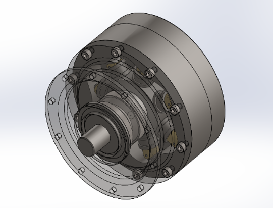
The physical design of the motor was driven by the need to preserve the harmonic optimisation benefits within a manufacturable and structurally robust package. In particular, the cam ring was designed to remain sufficiently stiff that elastic deformation would not significantly alter the optimised cam geometry. Finite element analysis later confirmed a maximum radial deformation of less than 1.13 , ensuring that structural compliance had a negligible influence on the predicted torque ripple characteristics.
Rather than treating sealing as an isolated mechanical feature, the sealing system was designed as a coupled hydro-mechanical subsystem. Hydraulic leakage is highly sensitive to seal clearance, exhibiting an approximate cubic relationship:
where is the effective clearance height. Consequently, achieving zero leakage is neither physically practical nor desirable, as eliminating clearance entirely greatly increases the risk of thermal seizure and boundary lubrication failure. To balance sealing performance with long-term reliability, a three-stage redundant sealing architecture was developed:
- Primary C-Channel Elastomer: A pressure-responsive C-channel elastomer that deforms elastically under hydraulic loading. Its primary functions are to accommodate structural deflection, compensate for manufacturing tolerances, and maintain adaptive sealing throughout the operating pressure range.
- Secondary PEEK O-Ring: An independent sealing barrier with excellent thermal stability, wear resistance, and chemical compatibility with hydraulic fluids. This stage provides redundancy should the primary elastomer experience degradation during long-term operation.
- Metallic V-Type Backup Seal: A pressure-activated metallic V-seal where the normal sealing force increases proportionally with hydraulic pressure (, where is the effective pressure-activated sealing area). Under elevated operating pressures, this mechanism automatically increases contact pressure, providing a passive fail-safe sealing response.
The layered sealing strategy decouples sealing reliability from extremely tight manufacturing tolerances. By permitting slightly larger operating clearances, the design maintains stable hydrodynamic lubrication while avoiding excessive leakage or seizure risk.
Note on Optimisation: The framework evolved iteratively alongside the development of the C++ simulation environment. The final implementation represents a balance between mathematical rigour and computational practicality.
The optimisation problem was formulated as a constrained hybrid global-local search operating on a reduced spline parameterisation. The complete design vector is
consisting of 20 B-spline control points, valve phase , valve opening width , and valve overlap . Valve timing was optimised simultaneously with cam geometry because phase mismatches between piston motion and port opening produce severe commutation shocks that cannot be eliminated through geometry alone. The entire optimisation pipeline is mapped out below:
To initialise the optimisation from a physically meaningful starting point, the cam profile was generated using a wrapped Fourier sine-power series:
This representation guarantees exactly six cam lobes, periodicity, and inherent continuity. The resulting curve was sampled at 360 locations before being converted into the 20-point B-spline representation used during optimisation.
Early optimisation experiments revealed an unexpected numerical artifact. Rather than converging toward smooth cam profiles, the optimiser consistently drove the spline towards a nearly hexagonal geometry. From the optimiser's perspective, extended flat dwell regions minimise pressure variation and therefore reduce torque ripple. However, these flat regions are connected by sharp transitions, producing effectively infinite curvature and acceleration at the corners. Although mathematically favourable with respect to the objective function, these geometries are physically impossible to manufacture and would generate unacceptable dynamic loading. The emergence of this artifact demonstrated that optimisation alone is insufficient; appropriate geometric constraints are essential for producing physically meaningful solutions.
Each transient simulation requires the numerical solution of thousands of coupled nonlinear timesteps, making direct gradient-based optimisation computationally impractical. Furthermore, the objective landscape is highly non-convex due to discrete valve events, pressure discontinuities, nonlinear contact mechanics, and hydraulic compressibility. To address these challenges, a hybrid Bayesian optimisation framework was deployed across three distinct operational mechanics:
- Global Surrogate Model: A Gaussian Process (GP) with a squared exponential kernel constructs a probabilistic approximation of the 23-dimensional objective landscape. This surrogate predicts both the expected objective value and the associated uncertainty, enabling efficient exploration of promising regions without requiring expensive full simulations.
- Diverse Candidate Generation: Candidate solutions are generated using a diversified mutation strategy designed to balance exploitation and exploration. Each optimisation iteration produces candidates according to strict structural proportions: 60% local perturbations around the current best solution, 20% crossover with historically high-performing solutions, and 20% purely random exploration. This strategy reduces premature convergence while maintaining sufficient diversity to escape local minima.
- Local Refinement: The most promising surrogate predictions are refined using the Nelder-Mead simplex algorithm before being evaluated using the full transient physics simulator. This local optimisation stage improves convergence efficiency while avoiding unnecessary expensive simulations.
Although the initial optimisation objectives were derived from analytical frequency-domain metrics, the final optimisation strategy evolved through extensive empirical experimentation. Over several weeks of iterative development, the objective function weights and harmonic penalty terms were progressively refined.
Particular emphasis was placed on heavily penalising higher-order Fourier coefficients, through , which strongly correlate with rapid local curvature changes and poor manufacturability. These empirical refinements successfully redirected the optimisation away from the polygonal artifact and towards a family of solutions characterised by broad, smooth cam lobes, continuous curvature, improved manufacturability, stable hydraulic dynamics, and significantly reduced torque ripple. The resulting optimisation framework therefore combines physically informed modelling with practical numerical heuristics to produce cam geometries that are both dynamically effective and manufacturable.
07Team Contributions
Team Contributions
The foundational background research and preliminary architectural benchmarking were supported by a project partner. This included conducting the initial literature review to establish the state-of-the-art in radial piston motor configurations, as well as compiling the baseline comparative data for eccentric, crankshaft, and phased-rotor architectures that informed the early stages of the design matrix.
Additionally, the partner contributed to the final document assembly, handling formatting, figure integration, and structural editing to prepare the comprehensive technical report. This support allowed for a clear division of labor where the core systems engineering, physics derivation, and computational development could proceed uninterrupted, while ensuring the final deliverable was cohesively integrated.
08Engineering Process
Engineering Process
The development of the radial piston motor followed a nonlinear, iterative systems engineering workflow that progressed from architectural theory through mathematical modelling, numerical simulation, optimisation, structural verification, and finally system-level integration.
Rather than following a strictly sequential process, each phase informed and refined the others as new physical insights emerged. This iterative approach allowed analytical theory, computational modelling, and engineering judgement to converge towards a manufacturable and dynamically robust design.
Architectural Analysis & Harmonic Filtering. The initial phase focused on establishing a mechanically favourable design space before introducing geometric optimisation.
Multiple piston–lobe configurations—including 6/6, 7/5, 7/6, 8/6, and other candidate architectures—were evaluated to quantify the influence of harmonic phase dispersion resulting from coprime piston and lobe counts.
Frequency-domain analysis using the Fast Fourier Transform (FFT) demonstrated that the seven-piston, six-lobe (7/6) architecture provided the most favourable harmonic characteristics by naturally suppressing coherent low-order harmonic reinforcement.
Establishing an appropriate harmonic architecture at this stage ensured that subsequent optimisation could refine an already favourable design rather than attempting to compensate for fundamentally poor excitation characteristics.
Mathematical Model Development. Following architectural selection, the governing mathematical model of the coupled hydraulic-mechanical system was derived.
This phase established:
- The nonlinear mapping from geometric parameters to torque output.
- The mass-spring-damper interpretation of hydraulic compressibility.
- Chamber pressure evolution equations.
- Frequency-domain representations of torque and pressure harmonics.
- The primary optimisation objective functions.
The resulting reduced-order model captured the dominant physical mechanisms responsible for torque ripple while remaining computationally tractable for repeated optimisation loops.
Simulation Engine Development (C++). The analytical model was subsequently translated into a custom high-fidelity transient simulation environment implemented in C++.
A fixed-timestep numerical integrator operating with a timestep of 20 was developed to solve the coupled nonlinear ordinary differential equations governing piston dynamics, hydraulic pressure, valve flow, spring forces, friction, and fluid compressibility.
Because the hydraulic fluid was modelled using a bulk modulus of 1.4 GPa, the resulting system exhibited significant numerical stiffness.
To maintain simulation stability during aggressive valve transitions, a simplified pseudo-cavitation model was introduced. Whenever chamber pressure dropped below vapour pressure, the effective bulk modulus was temporarily reduced, allowing the simulation to remain numerically stable while preserving the essential physical behaviour.
This phase also introduced the Fourier-to-B-spline initialisation routine used to generate smooth, -continuous starting geometries for optimisation.
Optimisation Framework Development. With the transient simulation environment established, the hybrid Bayesian optimisation framework was constructed around the physics solver.
The optimisation architecture combined:
- Gaussian Process surrogate modelling.
- Probabilistic acquisition functions.
- Diversified candidate generation.
- Local refinement using the Nelder-Mead simplex algorithm.
A substantial portion of this workflow was devoted to identifying and resolving the polygonal (hexagonal) optimisation artifact.
Early optimisation runs consistently converged towards nearly polygonal cam profiles. Although these geometries appeared numerically favourable by artificially reducing pressure variation, they contained unrealistically sharp curvature transitions that violated both mechanical and manufacturing constraints.
Resolving this behaviour required replacing purely analytical objective weightings with empirically tuned harmonic penalty functions that discouraged excessive high-frequency curvature while preserving optimisation flexibility. The resulting optimisation process consistently converged toward smooth, manufacturable cam geometries.
Structural & Subsystem Validation (FEA). Once a dynamically stable cam profile had been synthesised, the geometry was translated into a fully parametric CAD assembly for structural verification.
Finite element analysis (FEA) was used to validate the rigid-body assumptions employed throughout the mathematical model.
The structural assessment evaluated:
- Hertzian contact stress.
- Fatigue life.
- Modal analysis.
- Bearing support deflection.
- Cam ring deformation.
These simulations confirmed that the optimised harmonic profile remained structurally stable under the intended operating pressure of approximately 450 bar, and that elastic deformation was sufficiently small to preserve the optimised cam geometry.
System Integration & Safety Verification. The final phase integrated the optimised motor into a complete hydraulic system model developed using Automation Studio.
The system model incorporated:
- Directional control valves.
- Hydraulic accumulators.
- Relay logic.
- Thermal management.
- Auxiliary hydraulic components.
Transient operating conditions were simulated to verify system behaviour during realistic switching events, pressure transients, and load changes.
This integration phase also formalised the operational safety requirements, engineering constraints, and standard operating procedures required for eventual physical implementation.
Iterative Development Flow. Although presented as a series of distinct engineering tasks, the project evolved through continual iteration between modelling, simulation, optimisation, and validation.
Insights gained during finite element analysis frequently informed changes to the optimisation framework, while improvements to the simulation environment often motivated revisions to the mathematical model itself.
This iterative systems engineering methodology ensured that the final design represented not only an optimised mathematical solution but also a structurally feasible, manufacturable, and physically representative engineering system.
09Results
Results
The project delivered a fully validated high-torque radial piston hydraulic motor design optimised for low-speed, high-pressure industrial applications. The final design successfully balanced the competing requirements of torque smoothness, structural durability, volumetric efficiency, hydraulic stability, and manufacturable geometry.
The system features the following primary operating parameters:
- Operating Pressure: 450 bar
- Flow Rate: 180 L/min
- Hydraulic Power: Approximately 135 kW
- Architecture: Seven-piston, six-lobe cam-ring configuration
System-level integration testing performed in Automation Studio confirmed stable bidirectional operation, effective transient pressure spike attenuation through accumulator integration, and reliable emergency shutdown behaviour. Additionally, the thermal management system maintained hydraulic fluid viscosity within acceptable operating limits, preventing thermal degradation and runaway behaviour during sustained high-load operation.
Harmonic Architecture Validation. The influence of piston-to-lobe harmonic architecture was quantitatively validated through frequency-domain analysis. The selected 7/6 coprime configuration achieved an and a . Compared with the non-coprime 7/7 baseline (), the selected architecture achieved a reduction of greater than 99% in RMS torque ripple, confirming that coprime configuration is a fundamental design requirement before geometric optimisation can be effectively applied.
Optimisation Artifact Resolution. During geometric optimisation, a critical failure mode emerged where the B-spline control points progressively collapsed towards a hexagonal (polygonal) cam profile. Although numerically favourable due to reduced harmonic excitation, this geometry introduced unrealistic curvature discontinuities and was physically unmanufacturable. The issue was resolved through the implementation of empirically tuned high-frequency harmonic penalties, particularly targeting coefficients through . These constraints redirected the optimiser away from artificial polygonal solutions and towards smooth cam geometries with physically achievable curvature distributions.
Structural Integrity (FEA): Finite element analysis validated the rigid-body assumptions used throughout the mathematical and optimisation models. The structural parameters confirm that geometric integrity is fully preserved under peak loading conditions.
Component Deformation & Fatigue Performance. The physical sub-assemblies were verified across four distinct engineering metrics to guarantee mechanical viability:
- Cam Ring Rigidity: Under peak loading, the maximum cam ring deformation was limited to () with a maximum cam stress of . This negligible deformation confirms that structural compliance does not significantly alter the optimised harmonic behaviour.
- Dynamic Stability Margin: Modal analysis identified the first significant structural natural frequency at . At an operating speed of 600 RPM, the primary rotational excitation frequency is only approximately 10 Hz. With dominant harmonic content remaining significantly below the first structural mode, the design demonstrates a substantial margin against resonance-induced amplification.
- Interface Contact Stress: Localised stress analysis of the piston and cam interface identified a maximum piston wall stress of () and a maximum structural deflection of . Fatigue analysis predicts a service life exceeding loading cycles under nominal operating conditions.
- Bearing and Support Alignment: Shaft support analysis demonstrated that alignment requirements were maintained under maximum operating loads. The maximum bearing support deflection was bounded at (), yielding a calculated bearing fatigue life of of continuous operation at 600 RPM.
Simulation Engine Performance. The final simulation framework successfully stabilised a highly stiff transient hydraulic model incorporating compressible fluid dynamics, nonlinear valve flow, piston inertia, hydraulic stiffness, and transient pressure effects. The solver successfully completed repeated optimisation evaluations without numerical divergence, enabling practical integration with the hybrid Bayesian optimisation framework.
| Parameter | Performance & Solver Boundaries |
|---|---|
| Fluid Bulk Modulus | 1.4 GPa |
| Integration Timestep | 20 µs |
| Simulation Duration | 3 shaft revolutions |
| Steps per Evaluation | 15,003 steps |
Final Assessment. The completed design demonstrated that combining harmonic architecture optimisation, physically informed mathematical modelling, custom transient simulation, hybrid numerical optimisation, and structural FEA validation can produce a radial piston motor architecture with significantly reduced torque ripple while maintaining mechanical robustness and manufacturability. The final system represents a complete engineering workflow from theoretical analysis through computational design and structural verification.
10Reflection
Reflection
This project served as a rigorous exercise in managing the friction between mathematical idealization and physical reality. The most profound lesson was recognizing that multi-domain engineering systems cannot be optimized in isolation. Early in the derivation phase, it is tempting to treat efficiency, ripple, and structural stiffness as independent variables to be maximized. However, the coupled dynamics of the motor—specifically the realization that reducing leakage to improve volumetric efficiency simultaneously removes critical hydraulic damping, thereby amplifying pressure oscillations—forced a shift in mindset. Successful engineering in this context is not about maximizing individual metrics, but about finding a constrained equilibrium where competing physical mechanisms cancel each other's worst behaviors.
The most valuable failure encountered during the development process was the "hexagonal cam" artifact. Watching the Bayesian optimizer confidently converge on a mathematically perfect, physically absurd polygon was a turning point in my understanding of algorithmic search. It highlighted a fundamental truth about applied optimization: an objective function will ruthlessly exploit any loophole in your constraint formulation. The optimizer did not fail; it perfectly solved the exact equation I gave it. The failure was in my translation of "smooth torque" into mathematical terms. Fixing this required stepping away from pure analytical weights and empirically tuning high-frequency penalty terms to essentially teach the optimizer about manufacturability and infinite jerk limits. It reinforced the principle that constraints are not just boundaries; they actively define the topology of the feasible design space.
From a computational strategy perspective, the value of the Gaussian Process surrogate model cannot be overstated. Evaluating a single design candidate required solving 15,003 tightly coupled, non-linear ODEs at a 20 µs timestep to capture water-hammer effects. Navigating a 23-dimensional design space using brute-force gradient descent or grid search was computationally impossible. The hybrid GP/Nelder-Mead architecture was not chosen merely for academic elegance, but out of absolute necessity. It allowed the system to learn the "shape" of the cost landscape from a sparse set of expensive simulations and exploit that knowledge intelligently.
If I were to scale this project with additional time and resources, my primary focus would be closing the loop between the structural and hydraulic domains. Currently, the workflow operates sequentially: the C++ optimizer assumes rigid bodies to find the cam geometry, and FEA validates the deformation post-optimization. Given GPU access (e.g., CUDA-based parallel evaluation), I would implement a differentiable physics engine or a Physics-Informed Neural Network (PINN) that could embed the 1.13 µm FEA-predicted deflections directly back into the transient hydraulic solver as real-time boundary condition updates. Furthermore, replacing the pseudo-cavitation model (the 90% bulk modulus drop) with a true differentiable two-phase flow model would eliminate the remaining source of simulation uncertainty, allowing the optimizer to safely explore aggressive valve timing overlaps that are currently bounded by conservative safety margins.
Ultimately, this work solidified my conviction that optimization algorithms cannot rescue fundamentally poor architectural decisions. The success of the final 7/6 motor design was not a product of computational power, but a product of spending the necessary time upfront to ensure the underlying physics architecture was inherently harmonically stable before the optimizer was ever allowed to touch it.
Engineering Dashboard
Live data visualisations—simulation results, FFTs, optimisation progress, and control-system response.
Engineering Deliverables
Version-controlled artefacts produced across this programme.
Parametric SolidWorks CAD Package
Individual — Final optimized motor geometry and FEA setup files.
Optimisation Engine Source Code
Individual — Visual Studio C++ optimisation algorithms and simulation scripts.
Explore more engineering systems