Engineering a Magnetic Bottle for a Star
Fusion requires plasma temperatures exceeding one hundred million kelvin—far beyond the limits of any material container. This article explores how tokamaks use charged-particle dynamics, helical magnetic fields, plasma current, MHD equilibrium, heating, stability, and turbulence control to construct a magnetic bottle capable of reaching fusion conditions.
22
minutes
4,312
words approx.
5
indexed topics
23 AUG
2026
The Tokamak — Part I: Engineering a Magnetic Bottle for a Star
Fusion is often introduced using an equation so compact that it hides almost the entire engineering problem.
For the deuterium-tritium reaction,
two isotopes of hydrogen combine to form a helium nucleus and a neutron. The products possess slightly less mass than the reactants, and that difference is released according to
At first glance, the reaction appears almost deceptively simple. There is no combustion chemistry to sustain, no rotating machinery required at the point of energy release, and no long chain of intermediate chemical reactions between fuel and useful heat. If two light nuclei can be brought sufficiently close together, the strong nuclear force takes over and the resulting mass defect appears as kinetic energy.
Yet this apparently simple requirement creates one of the most difficult coupled-system problems in modern engineering.
Deuterium and tritium nuclei are both positively charged. Before they can approach the femtometre-scale distances where the strong nuclear force becomes dominant, they must first move through an electrostatic potential that strongly repels them. Achieving a useful reaction rate therefore requires ion energies corresponding to temperatures on the order of
At these temperatures the fuel is no longer an ordinary gas. It becomes a plasma: a mixture of free electrons and positively charged ions whose behaviour is dominated by electromagnetic forces. [5][1]
No conventional material can simply surround such a fuel. Steel, tungsten and advanced ceramics may be engineered to survive intense radiation and transient heat fluxes, but none can act as a conventional wall in direct contact with a hundred-million-kelvin plasma. [1][5]
The reactor must therefore contain its fuel without allowing the fuel to touch the reactor.
The tokamak solves this problem using magnetic confinement. Charged particles spiral around magnetic field lines rather than travelling freely across them. A magnetic field can therefore perform the function of a wall without physically contacting the plasma.
However, this is only the beginning.
A straight magnetic field has open ends. Closing it into a torus eliminates those end losses, but introduces magnetic-field gradients and curvature. Those gradients create systematic particle drifts. Correcting the drifts requires the magnetic field to be twisted. The twist requires a substantial current flowing through the plasma itself. That current changes the equilibrium, introduces new instabilities and ties the magnetic configuration directly to plasma temperature through electrical resistivity.
Increasing plasma pressure improves fusion performance, but pushes the system toward magnetohydrodynamic stability limits. Increasing heating improves reactivity, but changes conductivity and current profiles. Improving thermal confinement reduces power loss, but often creates steeper gradients capable of driving edge instabilities.
The tokamak is therefore not simply a magnetic bottle.
It is a coupled electromagnetic system in which particle dynamics, plasma current, pressure, magnetic geometry, heating, turbulence and stability must remain compatible simultaneously.
This article develops that chain from the beginning: why fusion requires such extreme conditions, how magnetic fields can replace a material wall, why a simple toroidal field is insufficient, how tokamaks create helical magnetic geometry, and why the problem eventually becomes one of controlling a conducting fluid rather than merely trapping individual particles.
The Coulomb Barrier
The first engineering problem appears before the tokamak itself is considered.
Two nuclei carrying charges and experience an electrostatic potential
As the nuclei approach one another, the potential rises rapidly.
For deuterium and tritium, [5][1]
which makes the D-T reaction comparatively favourable among charged nuclear fuels. Even so, the electrostatic repulsion is enormous on nuclear length scales.
Fusion becomes possible only when the nuclei approach to distances of order
where the short-range strong nuclear interaction becomes dominant.
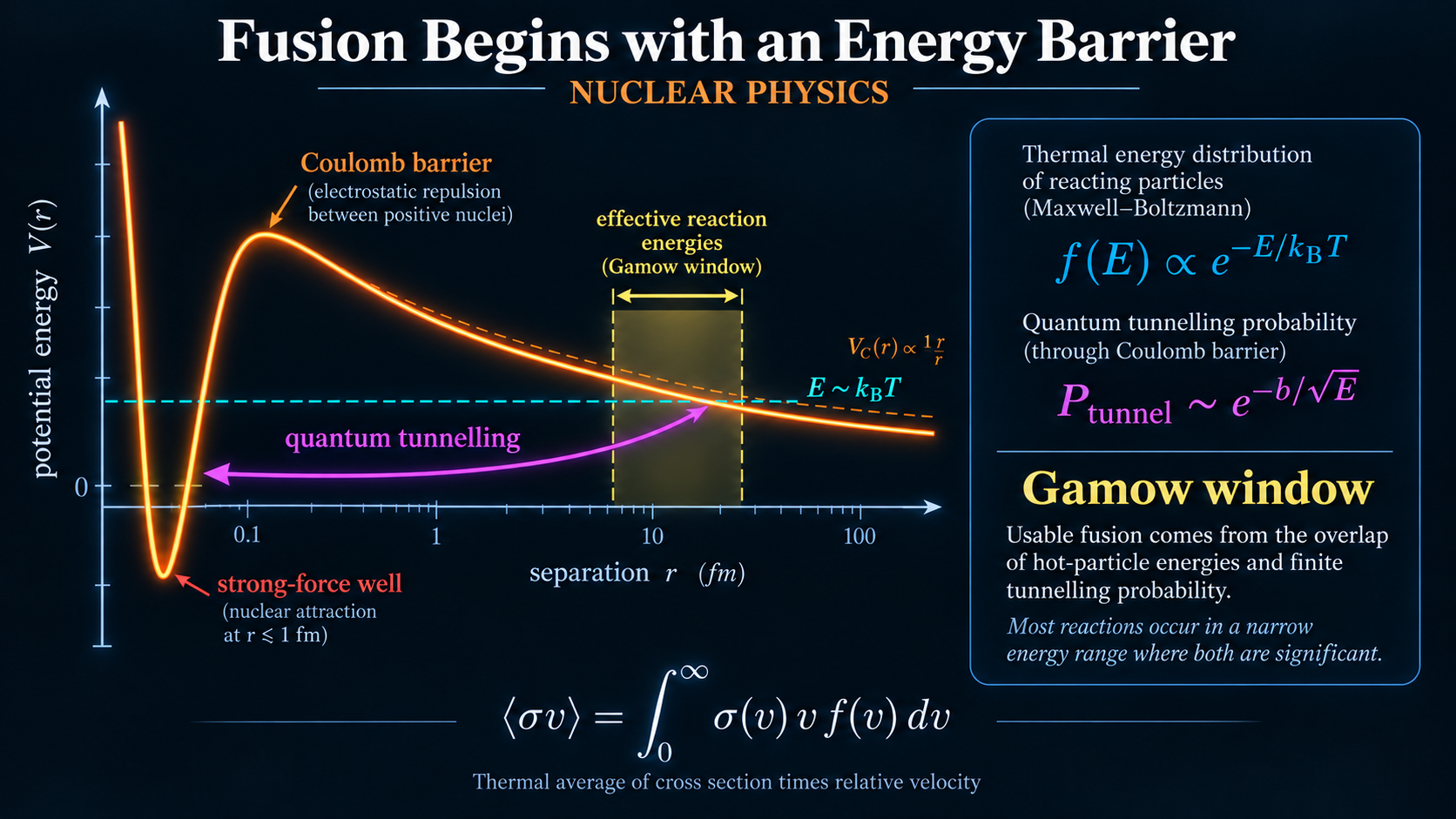
A purely classical interpretation would suggest that each nucleus must possess enough kinetic energy to climb directly over the Coulomb barrier. If this were the complete picture, useful thermal fusion would require even more extreme temperatures.
Quantum mechanics changes the situation.
A particle encountering a region where
does not simply stop at the classical turning point. Its wavefunction penetrates into the forbidden region and decays approximately as
where
The probability becomes small, but it does not become zero.
Two nuclei can therefore fuse even when they do not possess enough classical energy to overcome the entire Coulomb barrier.
This behaviour appears in the approximate fusion cross-section
where the exponential term describes Coulomb-barrier penetration and contains the more slowly varying nuclear contribution.
However, the plasma does not contain ions all travelling at one energy.
Their energies are distributed approximately according to a Maxwellian distribution,
This creates an important competition.
At low particle energy, the plasma contains many ions, but the probability of tunnelling through the Coulomb barrier is extremely small.
At high particle energy, tunnelling becomes considerably more likely, but only a small fraction of particles occupy the high-energy tail.
The product of these effects produces the Gamow window: the range of particle energies responsible for most of the fusion reactions.
The useful engineering quantity is therefore not the reaction cross-section alone, but the Maxwellian-averaged reactivity
For deuterium-tritium fuel, useful values of occur when the ion temperature reaches roughly
placing the plasma well above one hundred million kelvin.
This establishes the first requirement of a fusion reactor.
The fuel must be extraordinarily hot.
The second requirement follows immediately.
Because no material can directly contain that fuel, the reactor must prevent it from reaching the walls.
Replacing a Material Wall with the Lorentz Force
At fusion temperature, the fuel is ionised.
Instead of neutral atoms, the reactor contains charged ions and free electrons. This makes electromagnetic confinement possible.
A charged particle moving through electric and magnetic fields experiences the Lorentz force
Consider first a uniform magnetic field with no electric field. [1][2]
The magnetic force becomes
Because the cross product is perpendicular to the particle velocity,
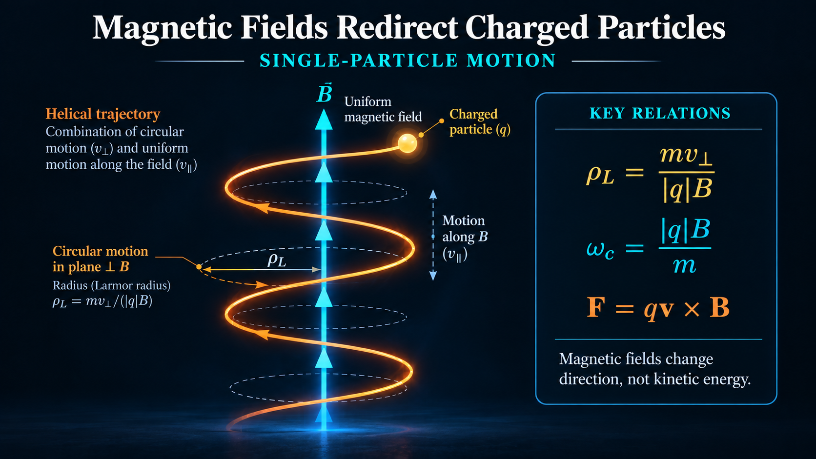
The magnetic field changes the direction of motion without directly changing the kinetic energy.
For the component of velocity perpendicular to the magnetic field,
which gives the Larmor radius
The corresponding cyclotron frequency is
Any component of velocity parallel to the field remains unaffected, so the complete trajectory becomes a helix wrapped around the magnetic field line.
This is the fundamental mechanism of magnetic confinement. [1][2]
If the magnetic field is sufficiently strong, the Larmor radius becomes very small compared with the dimensions of the reactor. Charged particles can travel freely along magnetic field lines, but their direct motion across those lines is strongly restricted.
A magnetic field can therefore function as a wall.
However, this simple picture immediately reveals another problem.
A straight magnetic field has open ends.
Particles may remain constrained radially, but they are still free to stream parallel to the field and eventually escape.
A practical confinement system therefore needs either an end-loss solution or a closed magnetic geometry.
For the tokamak, the solution is geometric.
The magnetic field is bent into a torus so that the field lines return to themselves.
Closing the Ends Creates a New Loss Mechanism
Closing the magnetic field into a torus eliminates the open ends. [1][2]
A charged particle travelling parallel to the magnetic field can now continue circulating around the machine rather than escaping along an axial direction.
At first glance, this appears to solve the confinement problem.
Unfortunately, bending the field introduces an unavoidable asymmetry.
For an ideal toroidal magnetic field,
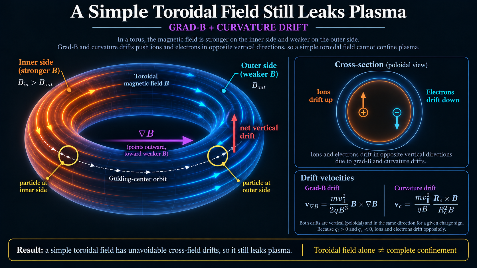
The field is stronger on the inner side of the torus and weaker on the outer side.
Therefore,
A charged particle no longer completes its gyro-orbit in a uniform field. One side of the orbit occurs in a stronger magnetic field than the other, and the guiding centre develops a net drift.
One contribution is the grad- drift,
The curvature of the magnetic field produces another contribution,
Both drifts depend upon the sign of the particle charge.
Ions and electrons therefore drift in opposite directions.
This creates charge separation.
Charge separation produces an electric field.
The combination of electric and magnetic fields then introduces the familiar
drift,
The simple torus has therefore solved one confinement problem and introduced another. [1]
This is one of the recurring patterns in tokamak engineering.
The correct response is often not to make an existing component stronger, but to alter the architecture of the complete system.
Increasing the magnitude of the purely toroidal field would reduce some orbit sizes, but it would not eliminate the geometric asymmetry responsible for the drift.
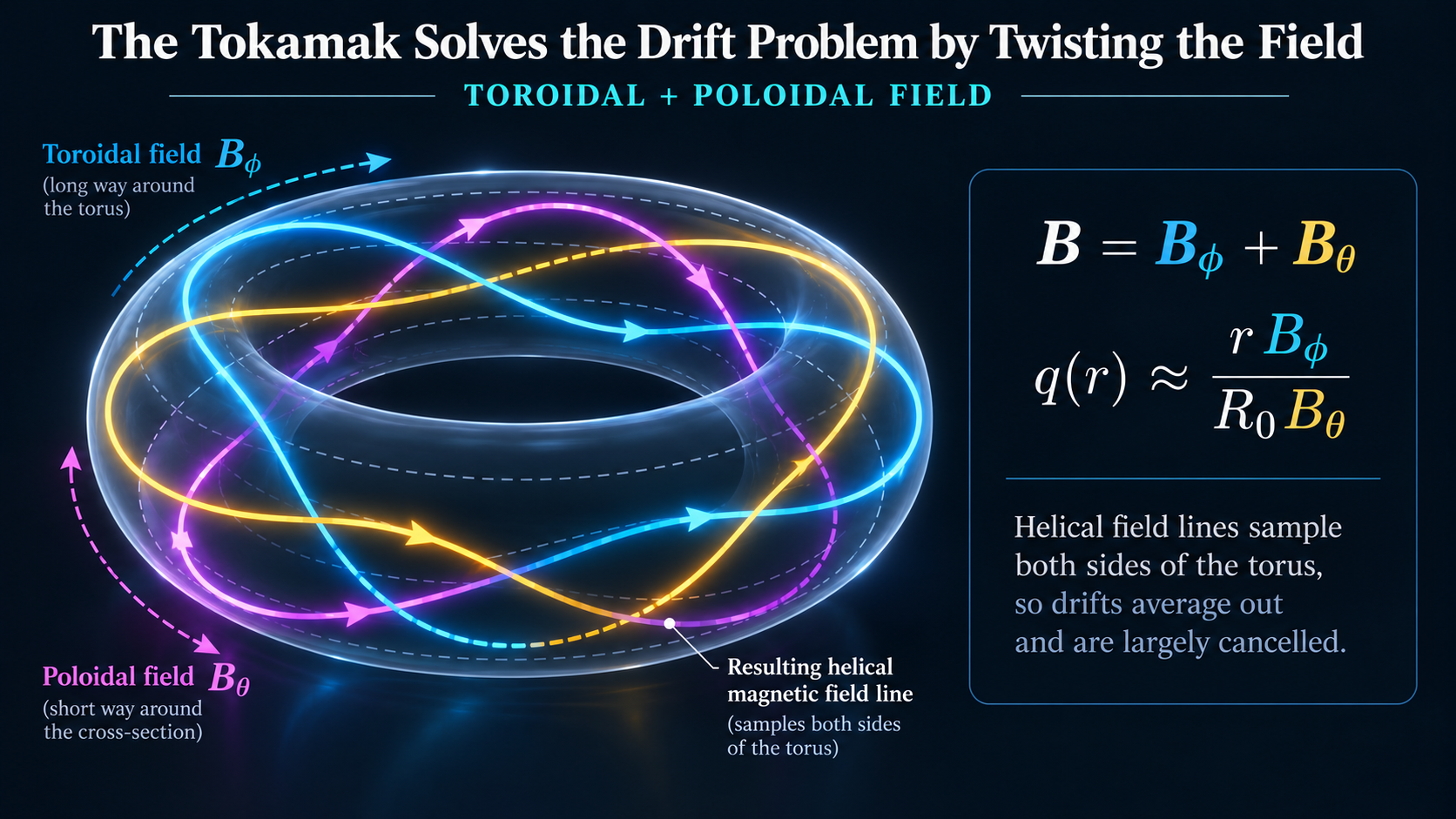
The field itself has to be twisted.
The Tokamak Trick: Twist the Magnetic Field
A tokamak combines two principal magnetic-field components. [1][2]
External toroidal-field coils generate the dominant field
A second magnetic component wraps around the plasma in the poloidal direction,
The total field becomes
The resulting field lines no longer follow simple circles around the torus.
They become helices.
A field line that begins on the weak-field outer side of the torus eventually moves through the strong-field inner side and back again. A charged particle following that field line therefore samples both regions of the magnetic geometry.
The systematic drift associated with the toroidal asymmetry is averaged over the orbit instead of accumulating indefinitely in one direction.
This does not eliminate every transport mechanism. Real plasmas still exhibit collisions, trapped-particle behaviour, turbulence and a range of collective effects.
However, the helical field removes the most obvious loss mechanism that makes a purely toroidal field unusable.
The remaining question is how the poloidal field is produced.
Tokamaks obtain a significant part of it from the plasma itself.
A large toroidal current is driven through the fuel.
That current generates the poloidal magnetic field.
The plasma is therefore no longer simply the object being confined. [1][2]
It becomes part of the confinement system.
The Plasma as a Transformer Secondary
The traditional tokamak current-drive mechanism is inductive. [1][2]
A central solenoid acts as the primary winding of a transformer.
The plasma behaves as a single-turn secondary winding.
Changing magnetic flux through the centre of the machine induces an electric field according to Faraday's law,
The induced toroidal electric field drives the plasma current
For a simplified circular plasma, the resulting poloidal magnetic field scales approximately as
At this point, several previously separate quantities become linked.
The toroidal field is set primarily by the external magnet system.
The poloidal field depends strongly upon the current flowing through the plasma.
The plasma current depends upon the induced electric field and plasma resistivity.
Plasma resistivity depends strongly upon temperature.
Temperature depends upon heating and transport.
A thermal change can therefore propagate into the magnetic configuration of the reactor.
This is an important conceptual transition.
The plasma is not a passive load placed inside a magnetic machine.
It is simultaneously
- the nuclear fuel,
- an electrical conductor,
- a current-carrying magnetic element,
- and a fluid whose pressure influences the magnetic equilibrium.
The amount of magnetic-field twist is commonly described by the safety factor
Conceptually, describes the relative toroidal and poloidal winding of a magnetic field line.
A field line near
travels approximately twice around the toroidal direction for each poloidal circuit.
More importantly,
varies across the plasma radius.
This produces magnetic shear.
Magnetic shear can improve or degrade different classes of instability and transport, depending upon the local conditions.
Particular rational values,
also create surfaces on which perturbations with matching toroidal and poloidal mode numbers can align with the magnetic geometry.
The same helical field that improves single-particle confinement therefore establishes the structure that later governs collective plasma stability.
At this point, following individual particles is no longer enough.
The plasma has to be treated as a conducting fluid.
From Charged Particles to Magnetohydrodynamics
A reactor-scale plasma contains an enormous number of interacting charged particles.
For many of the behaviours that determine reactor operation, it is more useful to describe density, pressure, current and bulk velocity as continuous fields than to follow individual ions and electrons.
This leads to magnetohydrodynamics, or MHD. [1]
A simplified momentum equation is
The left-hand side describes the acceleration of the plasma fluid.
The pressure-gradient term,
drives expansion.
The electromagnetic body force,
provides magnetic confinement.
For a stationary equilibrium,
This is the central force balance of the magnetic bottle.
The hot plasma pushes outward.
The magnetic field pushes back.
However, the magnetic force contains more physical structure than a simple restoring pressure.
Using Ampère's law,
and a vector identity,
The first term behaves like a magnetic pressure,
while the second behaves like magnetic tension.
This gives a useful physical interpretation.
The field behaves somewhat like an elastic electromagnetic structure.
Compressing magnetic field lines raises the magnetic pressure.
Bending them produces tension that attempts to straighten the field.
The plasma therefore loads the magnetic field rather than merely existing inside it.
A common measure of this loading is the plasma beta,
Higher is desirable because it means more plasma pressure can be supported for a given magnetic field.
Fusion performance benefits from high pressure.
However, plasma pressure is also a source of free energy for instability.
The drive for better fusion performance therefore pushes directly toward the stability boundary.
The Plasma Shape Is an Electromagnetic Equilibrium
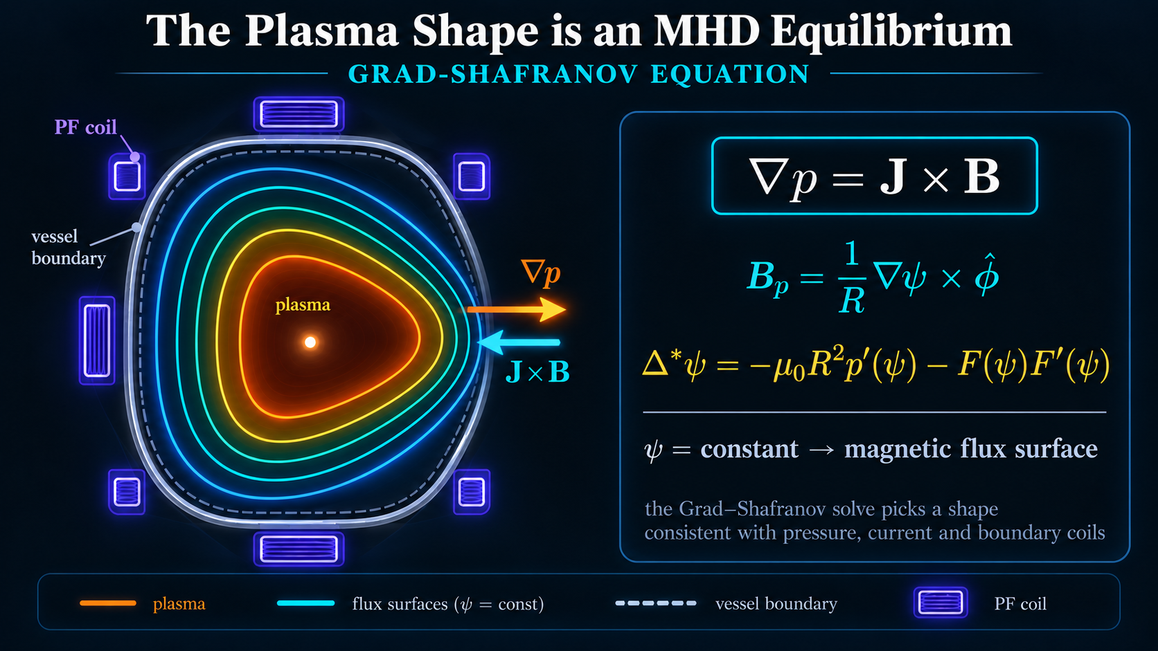
The familiar D-shaped cross-section of a modern tokamak is not simply a convenient vessel geometry.
It is the result of an electromagnetic equilibrium.
Assuming toroidal symmetry,
the magnetic configuration can be described using a poloidal flux function,
The poloidal field can be written
An important consequence follows:
Magnetic field lines therefore remain on surfaces where
These are the nested magnetic flux surfaces that define the plasma equilibrium.
Combining the flux representation with Maxwell's equations and MHD force balance produces the Grad-Shafranov equation,
Solving this equation determines the axisymmetric equilibrium compatible with the pressure distribution, current profile and imposed magnetic boundary conditions.
External poloidal-field coils alter those boundary conditions and therefore influence quantities including
- radial position,
- vertical position,
- elongation,
- triangularity,
- X-point location,
- divertor strike-point geometry.
The plasma shape is therefore not fixed by the physical walls around it. [1]
The machine establishes electromagnetic boundary conditions, and the plasma takes the equilibrium shape permitted by those conditions.
This matters because the equilibrium changes when the plasma state changes.
Additional heating can increase temperature.
Temperature changes resistivity.
Resistivity changes current diffusion.
The current profile changes the poloidal magnetic field.
The magnetic equilibrium shifts.
The plasma can therefore move through a sequence of electromagnetic shapes even though the surrounding hardware has not physically moved.
Equilibrium Does Not Mean Stability
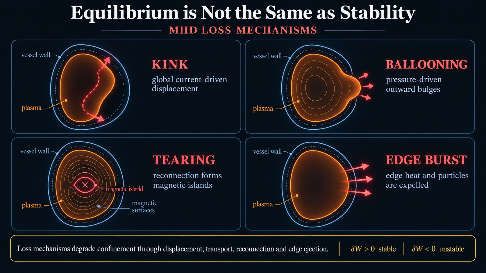
A plasma can satisfy force balance and still be unstable. [1]
A pencil balanced vertically on its point also satisfies force balance.
The smallest disturbance causes it to move away from the equilibrium instead of returning.
Tokamak plasmas face the same distinction.
Suppose the equilibrium is perturbed by a small displacement
In ideal MHD, the corresponding magnetic perturbation is
A powerful way to study stability is the MHD energy principle.
If every physically allowed perturbation increases the total potential energy,
the equilibrium is stable.
If at least one perturbation lowers it,
the plasma has found a direction in which the system can release free energy.
The disturbance grows.
This produces several major families of instability.
Kink Modes
A current-carrying plasma can bend as a large-scale structure.
The same current required to generate part of the confining magnetic field therefore stores free magnetic energy capable of destabilising the plasma.
Ballooning Modes
High plasma pressure is desirable because fusion performance improves with pressure.
However, pressure can drive local outward bulging in regions of unfavourable magnetic curvature.
The plasma behaves as though it is pushing through the confining field.
Tearing Modes
Ideal MHD assumes that magnetic topology remains frozen into the plasma.
Real plasmas have finite resistivity.
Magnetic reconnection can therefore occur around certain rational surfaces.
The resulting magnetic islands alter local field topology, degrade confinement and can grow into serious instabilities.
Edge Instabilities
High-confinement operation produces steep pressure gradients near the plasma edge.
Those gradients are useful because they allow the core to retain more thermal energy.
They are also potential sources of instability.
Rapid edge events can eject particles and heat toward the surrounding machine.
The stability problem therefore emerges directly from the quantities required for good fusion performance. [1]
Large current helps create the magnetic geometry but can drive current-related modes.
High pressure increases fusion performance but can drive pressure-related modes.
Strong edge gradients improve confinement but can destabilise the boundary.
A practical tokamak does not eliminate these quantities.
It operates as close as possible to their useful limits while remaining on the stable side of the boundary.
Heating a Plasma That Cannot Be Touched
Even a perfectly shaped and stable plasma would be useless if it could not reach fusion temperature.
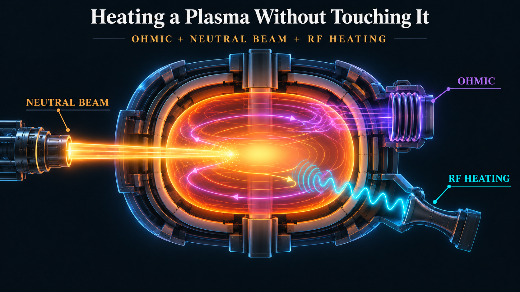
The first heating mechanism is built directly into the tokamak transformer. [3][1]
The plasma has finite electrical resistance.
Driving the plasma current therefore produces Ohmic heating,
During startup, this can provide substantial heating.
Unfortunately, the plasma becomes a better conductor as it becomes hotter.
For a fully ionised plasma, Spitzer resistivity scales approximately as
As the electron temperature rises,
The success of Ohmic heating therefore makes Ohmic heating less effective.
Auxiliary heating systems become necessary.
Neutral Beam Injection
Neutral-beam systems begin by accelerating charged particles through a large electric potential, [3]
The accelerated ions are then neutralised.
Because a neutral particle has
the confining magnetic field no longer deflects it strongly.
The beam can penetrate into the plasma.
Collisions then re-ionise the particles and transfer their kinetic energy into the fuel.
Neutral beams can provide many megawatts of heating.
They also inject momentum and can drive plasma current.
This is important because the system influences more than temperature.
It can modify plasma rotation, current profile and therefore stability.
Electron and Ion Cyclotron Heating
Charged particles naturally gyrate at
For electrons,
while for ions,
Electromagnetic waves launched near these resonances can transfer energy selectively to particular particle populations. [3]
Electron Cyclotron Resonance Heating can deposit energy with high spatial precision and can also drive local current.
Ion Cyclotron Resonance Heating performs a similar role for ion populations.
The heating system therefore becomes more than a thermal input.
It also becomes a profile-control actuator.
Once again, subsystem boundaries become less distinct.
A neutral beam influences temperature, current and rotation.
An RF system influences temperature and local current.
A change in heating therefore propagates into equilibrium and stability.
The Transport Problem
A simple charged-particle model predicts extremely good confinement.
The Larmor radius is small, and classical cross-field diffusion scales approximately as
If classical transport were the dominant mechanism, maintaining fusion temperatures would be considerably easier.
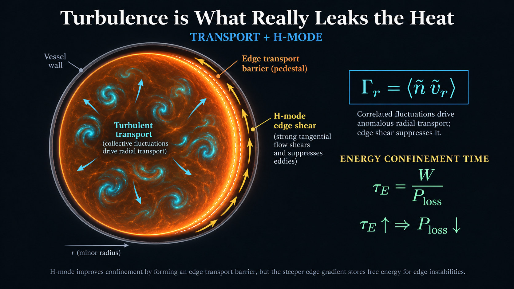
Real plasmas lose particles and thermal energy much faster. [1][4]
The dominant cause is turbulence.
The plasma contains strong gradients in density, temperature and pressure.
Those gradients store free energy.
Small fluctuations can extract that energy and grow.
Write the density as
and radial velocity as
The turbulent radial particle flux contains the correlation
The important quantity is not simply the magnitude of either fluctuation.
It is their correlation.
If above-average density tends to move outward while below-average density tends to move inward, a net radial particle flux appears even when the mean radial velocity is small.
Equivalent mechanisms transport thermal energy.
This is why a tokamak cannot be understood solely from individual particle orbits.
The magnetic field may prevent a single ion from travelling directly across the machine, yet collective fluctuations can still move energy outward much more effectively than classical orbit theory predicts.
The engineering problem therefore shifts again.
The magnetic field must not only confine particle trajectories.
The reactor must also suppress or control collective transport.
H-Mode and the Cost of Better Confinement
One of the most important discoveries in tokamak operation was that sufficiently heated plasmas can transition into a higher-confinement state known as H-mode. [4][1]
Near the plasma edge, strong velocity shear disrupts turbulent structures before they can grow large enough to transport significant energy.
An edge transport barrier forms.
The energy confinement time,
increases.
Therefore,
for a given stored energy.
This is exactly what a fusion reactor needs.
Improved confinement means less external power is required to sustain a given plasma temperature, and more of the internally generated energy remains within the fuel.
However, the transport barrier also steepens the pressure gradient near the plasma edge.
The same change that suppresses turbulence therefore increases the free energy available to edge instabilities.
The objective is not maximum confinement in isolation.
It is the best confinement compatible with stability, exhaust and material limits.
This is a recurring design philosophy throughout tokamak engineering.
The reactor is rarely limited by whether one performance metric can be improved.
It is limited by whether that improvement remains compatible with the rest of the machine.
The Point Where the Plasma Becomes the Reactor
Until this stage, the plasma can be treated primarily as a magnetically confined system receiving energy from external sources.
Ohmic heating, neutral beams and radio-frequency systems deposit power.
Transport removes it.
A simplified energy balance is
Then the fusion rate becomes large enough for the reaction products themselves to matter. [5][3]
Each deuterium-tritium reaction produces an alpha particle carrying approximately
and a neutron carrying approximately
The neutron is electrically neutral.
The magnetic field cannot confine it.
It leaves the plasma.
The alpha particle is charged.
The same magnetic field that confines the fuel also confines the fusion product.
As the alpha slows through collisions, its kinetic energy is transferred back into the surrounding plasma.
A new heating term appears,
The energy balance becomes
At first glance, this is only one additional term.
Yet this seemingly modest change transforms the machine.
Fusion power depends strongly upon temperature.
Alpha heating depends upon fusion power.
Temperature has therefore begun influencing its own heating source.
The plasma is no longer merely the load of an external heating system.
It has become an internally heated nonlinear reactor.
Pressure changes with the burn state.
The current profile continues to evolve.
Transport changes the energy balance.
Stability boundaries move.
Neutron power begins loading the surrounding structure.
Tritium is consumed and must eventually be replaced.
The magnetic bottle developed throughout this article is therefore only the first half of the fusion problem.
Once alpha heating becomes significant, the tokamak must not only confine a star.
It must turn that confined star into a stable, fuel-sufficient and controllable power plant.
That is the problem developed in Part II.
References
Sources consulted for the technical claims in this article. Citation numbers refer to the bracketed references in the text.
- IAEA, Fusion Physics (2012), eds. Kikuchi, Lackner & Tran. — https://www-pub.iaea.org/MTCD/Publications/PDF/Pub1562_web.pdf
- U.S. Department of Energy, DOE Explains... Tokamaks. — https://www.energy.gov/science/doe-explainstokamaks
- ITER Organization, External heating systems. — https://www.iter.org/machine/supporting-systems/external-heating-systems
- Princeton Plasma Physics Laboratory, H-mode transition and edge turbulence simulation. — https://www.pppl.gov/news/2022/scientists-perform-first-basic-physics-simulation-spontaneous-transition-edge-fusion
- IAEA, Fundamentals of Fusion. — https://www-pub.iaea.org/MTCD/Publications/PDF/PUB1945_web.pdf